Technique
development ? in an instant with Imagine3D!
Imagine3D
ultrasonic simulation software allows you
to completely simulate your inspection method so that you can save
time and make fewer errors
Visualize
and confirm that your inspection technique is doing what you think
it's doing Imagine3D shows you exactly where
your ultrasonic sound field is going in a part using three dimensional
graphics that can be rotated to any viewing angle. All longitudinal
and shear-wave mode conversions can be displayed using different colors.
Simulated A-scans also provide the means of confirming signal strength
and position for comparison with the real thing.
Diagnose
difficult problems Because Imagine3D can handle
any number of longitudinal and shear mode conversions, it can accurately
identify where unexplained echoes are originating.
Right Click
on the image and deselect " Play" to stop the animation.
Never
order the wrong transducer again Imagine3D will model the sound
field of your existing transducer or it can tell you which transducer
to buy for any given inspection geometry. This eliminates
expensive errors when a transducer with the incorrect focal length
or beam-spread is ordered by mistake.
Clearly
and easily communicate your ideas with others Imagine3D provides simulated
inspection A-Scans and B-Scans as well as reports that you can use
to better communicate with your technicians and customers.
If fixturing is required, Imagine3D provides
a text printout that lists the probe angles, spacing and water-path
distances.
Imagine3D
is an excellent teaching tool Imagine3D makes it simple to
demonstrate how certain critical angles affect whether longitudinal
and shear waves can exist. Teachers can also ask students
to use Imagine3D to prepare and submit
a complete inspection simulation demonstrating that they understand
the material being taught.
Be more productive Its nice to be able to experiment and try things out before
committing to fixturing. Imagine3D takes
you through the same steps as you would experience in the real world
with the added benefit of being able to see where the sound is actually
going inside your inspection part.
The parts are your parts. The transducers can be anything
that you might have on the shelf or that you can order from a catalog.
Your successful inspection technique is whatever Imagine3D
allowed you to discover while experimenting with angles, mode conversions
and different focal lengths.
Performing
a simulated inspection involves these four simple steps:
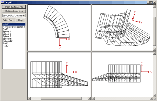
1
CREATE
OR IMPORT YOUR INSPECTION TARGET
2
ENTER
THE TRANSDUCER CHARACTERISTICS
Hover
over the different tabs to explore the transducer characteristics
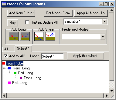
3
CHOOSE
THE INSPECTION MODES
4
MOVE THE TRANSDUCERS AS IF YOU WERE PERFORMING AN INSPECTION
and
Imagine3D can show you exactly where the sound is going in all
3 dimensions as well as present a simulated A-scan
Imagine3D
fully models and simulates...
Sound
Fields
can
be displayed as rays, pulses, wavefronts or beams
can
be reduced to a single main ray to reduce clutter
can
be rendered to show how amplitude is affected by diffraction
can
be advanced or retreated in time to compare the absolute time
position of every wavefront
will
change color when a mode conversion occurs, a new medium is entered
or whenever a new wave is generated
Inspection
Targets
can
be assembled from a list of primitive shapes such as blocks, rods,
tubes and spheres
can
be imported from 3D ACIS® SAT (Solid Model) CAD
drawings
can
be extruded or revolved as solids from 2D DXF CAD drawings
can
be selected from a library of stock objects and modified to match
the inspection part
Transducers
can
simulate both contact and immersion transducers of any frequency
supports
spherical, cylindrical and elliptical focusing
supports
transducer elements that are circular, elliptical or rectangular
in shape
can
show any number of rays on the X and Y axes, on the transducer's
edge or evenly spaced on the transducer's surface
Ultrasonic
Inspections
supports
both Pulse Echo and Pitch Catch ultrasonic methods
provides
simulated inspection A-scans and B-scans
takes
into account material properties such as long and shear velocity
can
link the send and receive transducers together or allow them to
be moved separately
can
follow the part surface at a fixed distance and automatically
stay normal to the surface
...with
an easy to use interface that
provides
a single button that automatically splits the screen into a front,
side, top and 3D view of the inspection
allows
the inspection part to be rotated, spun or tilted to any viewing
angle
uses
a simulated A-scan that can be rectified as RF, FW, HWP, or HWN
and convert Time of Flight to distance
utilizes
Workspaces that allow you to save and recall everything on your
screen so that you can resume your work later or transfer your
simulation to another person
provides
a powerful print preview that displays exactly how the printout
will appear
provides
a full text description of probe angles, probe positions, medium,
modes and sound path lengths
can
export a simulation to share your results with people who do not
own Imagine3D, using our FREE I3DViewer software
ACIS and SAT are the registered trademarks of Spatial Technology
Inc.
Click
here to request more information or a quote.